
By far the most frequently asked question concerning an old clock made by the Standard Electric Time Co. is, "How many volts does it require?" Unfortunately this is not an easy question to answer. Some self-proclaimed experts will authoritatively state "3 volts", while others will say "24"; many owners will simply connect up a line cord and plug the clock into the wall, often to observe smoke pouring out within a few seconds. In fact, 3 volts DC, 24 volts DC and 110 to 125 volt 60 cycle AC are only some of the many voltages and currents used by "Standard" clocks made over the years. The company even built a few master clocks requiring BOTH AC and DC inputs (of not necessarily the same voltage) to be fully functional.
Unlike certain other makers, The Standard Electric Time Co. rarely supplied their pendulum-type master clocks with name plates indicating voltage and current. Only a very few of the last ones made after World War II have this information source.
Theoretically, it would be a simple matter to determine the voltage by experimenting with a variable-voltage DC power supply. In practice, however, many master clock movements have a winding mechanism so badly out of adjustment that it will not function at all on the intended voltage-- especially if it has been tampered with. If the winding lever advances the ratchet wheel 2 teeth at a time, at least twice the normal voltage will be needed to wind the movement, and tremendous stress will be placed on the escapement and other parts as the clock then tries to overwind.
There are several distinct generations of master clocks, each with its own particular voltage requirements. The earliest master clocks supplied by The Standard Electric Time Co. were made by the Self Winding Clock Co. of New York and contained their regular rotary motor wound movement built to wind itself on 3 volts. When in 1892 Standard began assembling its own master clock movements using mostly parts made by Seth Thomas, it was logical that these movements too would use 3 volts for the winding operation, normally obtained from a pair of 1.5 volt dry cells connected in series. Unfortunately the minute-impulse winding mechanism devised by Standard proved a little less efficient than its predecessor, and the battery powering it would occasionally expire in less than a year. Since battery replacement is easier to keep track of and more practical if done on an annual basis before the clock may unexpectedly "run down", another dry cell was added together with a corresponding increase in coil resistance, placing the new voltage requirement at 4.5 volts. So if you have one of these early clocks and 3 volts isn't quite enough with the right mechanical adjustments, try 4.5. A 5 volt computer grade regulated power supply is close enough in this instance, but if you only need 3 volts, you can get a nice little plug-in unit from Radio Shack. Although the coils are fairly tolerant of excess voltage, you may expect somewhat diminished contact life if you use, say, 6 volts to wind a 4.5 volt clock.
Please note that so far we have discussed only the voltage used to wind the master clock. Figure 477 below shows how a typical early clock system was wired. Observe that each system function has its own battery to supply whatever voltage that particular feature would require. A company letterhead from the 1890's advertises, "From one to fifty clocks placed on single circuit." A 50-clock series circuit would need about 75 volts!
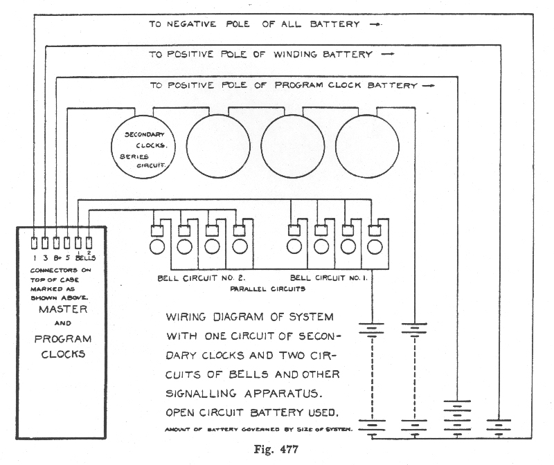
As clock systems evolved they became larger and more complex. By the teens, it made more sense to operate everything on a single voltage, obtained from a storage battery capable of delivering enough current to ring a whole school full of bells in addition to the clocks plus sometimes fire alarm and telephone systems. System voltage was often determined by the number of series type clocks controlled by the master. During this transitional period which lasted into the late twenties, the average new school building contained 15 to 18 clocks connected in series on two separate circuits. Thus, many 16 and 18 volt systems were installed. But if there were 12 clocks on just one circuit, it would likely be a 24 volt system, as would also be most of the systems in larger-than-average schools.
Information Concerning Straight Impulse (Non-Resetting) Secondary Clocks by The Standard Electric Time Co.
SERIES type clocks have a resistance of around 8 ohms and will operate alone on less than 2 volts, except in the larger sizes. A dozen or so series type clocks may be connected in series and operated from a 24 VDC master. In school installations, they would figure on allowing 2 volts per clock, to include the resistance of the interconnecting wires. In a typical collector residence installation, the interconnecting wires are much shorter, so up to around 15 series clocks may be run on 24 volts DC. The current should be in a range from 180 to 200 milliamperes and if it exceeds this, as it will with a smaller number of clocks than the optimum amount for the voltage supplied, you may add more clocks or use a 10-watt wirewound resistor of whatever ohm value will bring the current down to an acceptable level. System voltages of 12, 16 and 18 are not uncommon. If you place a voltmeter in parallel with an operating series clock, it will measure the voltage drop on the circuit caused by that particular clock excluding the interconnecting wires. A single 1.5 volt "D" cell is satisfactory for running a series slave having a self-contained electronic switching-only master (one supplying no output from its own battery cells), as there are no long runs of wiring between slave, master, and slave power source. (E. Howard advertised that their secondary clocks would operate on as little as a single volt!)
A 120 ohm resistor is connected in parallel with the coil assembly in SETCo series type clocks only, as a shunt for spark suppression. If the shunt resistor is burned out, it means that the clock at one time was connected to 110-125 volts AC, as these resistors do not overheat in normal use. (The rapidly reversing magnetic field of the low resistance coil assembly sets up an AC impedance that protects the magnet coils somewhat, but the higher resistance shunt, lacking a magnetic core, will quickly burn up when fed nearly 100 times the intended voltage.)
Other clocks were made to operate in PARALLEL on 12 or 24 VDC. 12-volt clocks have a resistance of 320 to 500 ohms and often do not have a shunt resistor, but if one is present, its value would be in the 3,000 ohm range. The 24-volt clocks have a resistance of around 1,250 ohms each, and if a shunt is present, its value would be around 5,000 ohms. A small number of 12 or 24-volt clocks will not function reliably if supplied by a relay having tungsten contacts, as most of these masters were designed to impulse many more slaves than the average collector will be connecting up.
Now, if your master has a clock circuit relay with tungsten contacts, well, this kind of contact doesn't handle currents of less than around 100 to 200 MA (depending on the alloy) very well. A single parallel (not series) slave clock with magnet wound for 12 or 24 volts just won't pass enough current for reliable operation. So in this case, you would need a suitable resistance in PARALLEL with the clock (try a 10-watt wirewound resistor in the 50 to 120 ohm range) OR you could bypass the relay and run the clock directly off the escapement contacts which are of platinum/iridium.
Series and parallel clocks cannot be mixed on the same circuit. In fact, when a master was built to operate both types of clock, there was a separate relay for each type. An example of this could be found in a school built in the early 1900's and equipped with series clocks throughout. Then in the 1930's a major addition was constructed and wired for the more recently introduced 3-wire automatically resetting clocks. A new master clock would be supplied for the automatic reset system, with a separate relay to operate the old series clocks in the original building. If a small number of 24VDC clocks are connected to a master with a series pilot clock on the same circuit, they will not pass enough current for the pilot clock to run. Trying to run both series and parallel clocks from a master with a single clock relay or none at all is considered a no-no. It was never done by the factory.
The resetting range of the AR-3 slave movement is limited to 25 minutes fast or slow. The master clock's hourly reset contact cam moves with the minute hand. Thus, if you push the hands of the master clock ahead, say, 5 minutes, the secondary clocks will advance 5 minutes at the next 59th minute as indicated by the master clock. Always be certain that the minute hand is directly over one of the minute marks as the second hand passes 60. A fully wound master clock will run 54 minutes without power unless it was built to run longer; motor-wound spring and weight-driven models were built to run without power for 12 hours, but these are rare, as is the 6-day model having 2 heavy weights. A 12-hour master with accumulator will advance the secondaries to the approximate time during the rewinding operation, with precise correction taking place at the next 59th minute after rewinding is completed.
The AR-3 (3-wire, single voltage) system was introduced in 1932 and originally designated AR. In 1948 the AR-2 (2-wire, 2-voltage) system was introduced at which time the earlier AR system became known as AR-3. Both are known as "gravity reset" systems and utilize a weight attached to the center arbor which upon falling enters a magnetic field to zero in on the precise minute intended (59th for the AR-3 and AR-2A and 58th for the AR-2). Please note that the later synchronous AC systems known as GR are not gravity reset systems; in this instance, GR stands for the initials of its inventor, George Riggs, Jr., son of George and Frances Riggs. George Sr. was the man who brought The Standard Electric Time Co. to Springfield, Massachusetts.
If your master clock has a buss bar on top marked RESET and 2 pairs of magnet coils forming a V at the bottom of the program movement it is an AR3 master; if there is no RESET bar, a single pair of magnet coils on the program and a small rectifier above the self-winding movement, it is an AR2 master.
Whichever it is, I can supply the appropriate wiring diagram and other copies of factory publications.
Pre-1929 master movements had a 60-tooth winding wheel, so that loss of reserve power was cumulative. This became a problem when the introduction of the dry plate rectifier did away with the use of automatically charged storage batteries. Repeated brief AC power failures would eventually stop the clock. So the number of teeth in the winding wheel was reduced to 59! Many older clocks had 59-tooth winding wheels installed to replace the 60-tooth ones. The whole idea was to gradually bring the clock back to a fully wound condition after a power outage not long enough to stop the clock. But once fully wound, the clock would be continually trying to overwind, with the force of the winding operation being transmitted through the stop-pins and train directly to the escapement, causing the escape wheel tooth engaged with the verge at that instant to wear short after 20 or so years. This would also happen using the 60-tooth winding wheel if if the winding cycle did not occur within a certain "window", as would often be the case since movements were usually assembled randomly in this regard. CONSEQUENTLY, over 50% of the master clocks now extant have worn-out or replaced escape wheels!
If the winding wheel has the same brass finish as the other wheels, it probably has 60 teeth. If it has a coppery finish, it is probably a replacement that has 59 teeth. If nickel-plated, it could be either 59 or 60. Most of the older clocks were converted to rectifier power, doing away with the storage battery. Sometimes the winding wheel was changed and sometimes it was not. Most of these changes were not properly done and many problems resulted. But even if properly done (which meant repositioning the back pawl assembly plus changing the coil assembly and winding lever rest post), the clock would still continually try to over-wind, putting undue stress on whatever escape wheel teeth were engaged during the winding operation.
With a 59-tooth wheel, the back pawl will sometimes catch the only the tip of a tooth and then let go between winding cycles. When this happens, the winding lever assembly takes up the force of the mainspring, flexing an earlier, thinner rest post more than a later, thicker one. Thus the armature must pull in from a greater distance under full load right from the beginning of its travel. Consequently, the clock may fail to wind, at least until the mainspring power diminishes somewhat-- if it does sufficiently to allow resumption of winding before the 54-minute reserve period has expired. The best solution (other than re-designing the winding mechanism as ITR/IBM did theirs) is to replace the coil assembly with a lower resistance and thus more powerful one, and the rest post with a thicker one, both being normally found on the later movements. More often than not, however, voltage was simply increased at the rectifier.
Each pallet of the verge has a locking face and an impulse face. If one or more teeth hit the impulse face causing the second hand to move backward, the escape wheel is worn out and needs to be repaired or replaced. (Should minimal wear be confined to just one or two teeth, stretching can be tried-- a risky procedure which may result in a broken-off tooth. But older wheels were made thinner and all teeth may be worn short to a lesser or greater degree.) Verges are hand-finished and no two are alike. This is why verge staff ears are pinned to the plate after the verge is fitted. Therefore, a replaced or tampered-with verge may not be in the right position. If an escape wheel is consistently worn out, its diameter is reduced, meaning the teeth are closer together-- so if the verge is brought in after removing the brass locating pins, the escapement will lock up before proper action is obtained; thus if individual teeth cannot be successfully stretched, the worn wheel must be replaced rather than re-surfaced to make all teeth the same radial length although shorter. All verges are finished for one specific distance between tooth-tips, so the escape wheel MUST be of the correct diameter-- not a few thousandths smaller.
Some clocks are found to contain a heavy-duty escape wheel with teeth that taper down to an end thickness of .010" instead the normal .005". Such a wheel can be readily identified by its heavy, straight-sided and tapered spokes. Apparently these wheels were supplied only as replacements and were introduced for that purpose after production of pendulum type movements was discontinued. They are not compatible with the old verges, many of which were crudely ground down to make them work with the new wheels. (Compatible replacement verges were available, but instead of being hardened they were plated with a hard metal which sometimes partially separates from the steel, leaving rough edges which accelerate wear!) Most old verges that are botched or badly worn can be resurfaced with excellent results, but it requires a special jig in combination with fine oilstones, polishing compounds and other tools, more skill than the average clock repair person has, plus lots and lots of patience; a potentially good verge can be ruined by taking off too much material too quickly.
HUB
Inside OD: 5/16" (.3125")
Outside OD: 1/2" (.500")
Thickness, large OD: 1/8" (.125")
Thickness, small OD: .080"
Thickness, total: .205"
ID: 1/8" (.125") (SOME ARE LESS ON EARLY CLOCKS)
WHEEL
OD: 1 9/16" (l.5625")
Thickness: 1/16" (.0625")
ID: 5/16" (.3125")
Portion of circumference occupied by each tooth tip: .005" (HEAVY DUTY: .010")
Number of spokes: 5
Number of teeth: 30
Rounded edge of pre-punched blank at front; sharp edge at rear
Large OD of hub at rear
Direction when viewed from front: clockwise
Type of escapement: Graham dead-beat
This table applies only to master movements having a helical mainspring of round wire, with a reserve of 54 minutes.
A = Application (pendulum type)
B = Diameter of mainspring when fully unwound and not installed (average between ID and OD)
C = Diameter of wire
D = Music wire gauge number -- NOT the same as AWG gauge numbers
E = Number of turns when fully unwound and not installed
F = Number of turns placed on spring during assembly
| A | B | C | D | E | F |
| Wood Rod | 7/16" | .022" | 9 | 20 | 4 |
| Hg2, Invar | 7/16" | .024" | 10 | 17+1/2 | 2+1/2 |
| Hg1, Hg3* | 7/16" | .026" | 11 | 15 | 3 |
*Beginning around 1930, the .026" mainspring was used in ALL movements with the 54 minute reserve. This was done to cut production costs. For applications requiring less power, reduce "F" specification given above to 1 or 2 turns. Situations requiring more power include "drop" contacts, 59 tooth winding wheel, 5 and 10 second duration contacts together on same movement, and seconds ticker attachment. But NEVER exceed 3 turns on this mainspring or the recommended number of turns on any other as given above. Reduce the number of turns by 1 if pendulum swing exceeds III on beat scale.
"F" figures given are based on the general observation that thickest and thinnest mainsprings listed have end loops opposite each other, while end loops of medium thickness springs are 180 degrees apart. Because of variable factors involving quality control, the effects of normal or excessive stress and aging characteristics of wire used, not all mainsprings are as specified here. For nonconforming mainsprings, the "F" specification should not exceed one-quarter turn additional. If it does, subtract one whole turn. Shortened mainsprings are best replaced.
Original specifications
Thickness: .005" - .006"
Width: 3/8"; some a bit less
Total thickness including brass ends: .085"
Working length of spring (average): 11/16"
Total length of spring: 1&7/16"
Total length of spring assembly: 1&1/2"
Distance between pins, center to center: 1&1/8"
Number of flush rivets at each end: 2
Same as Seth Thomas #2 Regulator suspension spring.
Original suspension springs have 2 flush rivets at each end to help secure ends to spring. These are omitted from recently manufactured replacement springs. They should not be. Complain!
Here's another pointer. The suspension post slot should be of uniform width from front to back. If it isn't, probably someone has been either prying or squeezing on the post to fit a replacement spring. Hopefully it hasn't been ruined by excessive bending or filing! Once uniformity has been restored, the new spring may need to be fitted. I have noted variations of a few thousandths in ORIGINAL spring ends. Ideally the replacement spring end should be the same dimension as the slot so when lubricated, it can turn easily on the pin with absolutely no slack. If it is loose but not loose enough for a shim, a little squeezing of the post is permissible, unless you find a spring that fits better. If too tight, the end thickness can be reduced by rubbing on a fine, large, flat single-cut file. Check frequently with a micrometer to make certain that you are not removing more brass from one point than another. If you are, vary finger pressure accordingly and continue checking as you go.
#1: (-) ALL BATTERY OR POWER SUPPLY. SOMETIMES MARKED (-). ON VERY EARLY CLOCKS MARKED "ZINC". GROUNDED TO MOVEMENT FRAME (EXCEPT ON RARE 110VDC MODELS)
#2: SIGNAL DURATION. FOUND ONLY ON MASTER CLOCKS CONTROLLING PROGRAM MOVEMENT(S) IN SEPARATE CABINET(S)
#2A: SIGNAL DURATION, LONG RING. OPTIONAL. FOUND ONLY ON MASTER CLOCKS CONTROLLING PROGRAM MOVEMENT(S) IN SEPARATE CABINET(S)
#3: (+) FOR WIND COILS. ON VERY EARLY CLOCKS MARKED "CARBON"
#4: PROGRAM MOVEMENT ADVANCE. FOUND ONLY ON MASTER CLOCKS CONTROLLING PROGRAM MOVEMENT(S) IN SEPARATE CABINET(S)
#5 ON SINGLE CIRCUIT MASTER CLOCKS WITHOUT SECONDARY CLOCK RELAY: INTERMITTENT (-) IMPULSE TO SECONDARY CLOCKS #5 ON MASTER CLOCKS WITH SECONDARY CLOCK RELAY: (+) FOR RELAY COIL
#6 (EXCEPT AR2 MASTER): (+) FOR PROGRAM MOVEMENT ADVANCE AND SIGNAL RELAY COILS. NORMALLY MARKED "+BPROG"
#7 (EXCEPT AR2 MASTER): INTERMITTENT (-) IMPULSE TO ADVANCE BATTERY CHARGER TIMER. NORMALLY MARKED "AUTO CHG". OFTEN INTERNALLY WIRED TO #4 #8 (EXCEPT AR2 MASTER): BELL OR PROGRAM RELAY CONTACTS. WHEN NOT EXTERNALLY CONNECTED TO #1, PERMITS THE USE OF CONTACTLESS AC SIGNALS OR THOSE OPERATING FROM A HIGHER VOLTAGE DC SOURCE. POWER SOURCE IN SUCH INSTANCE WIRED BETWEEN
#8 AND "BC" (BELL COMMON) TERMINAL; SIGNALS BETWEEN NUMBERED "B" AND "BC" TERMINALS. SOMETIMES DESIGNATED "TRANS" OR "BELL RELAY CONTACT"
(+) BUSS BAR: REPLACES SEPARATE TERMINALS 3, +BPROG, +BELLREL AND (SOMETIMES) 5. CONNECTED TO (+) SIDE OF POWER SUPPLY. RETURN WIRES FROM COMMON VOLTAGE DC CIRCUITS GO HERE
"C" TERMINALS: INTERMITTENT (-) IMPULSE TO SECONDARY CLOCK CIRCUITS. IF PILOT CLOCKS ARE PRESENT, IT MUST BE DETERMINED WHETHER THEY ARE SERIES OR MULTIPLE. IF BOTH ARE PRESENT IN THE SAME MASTER, THERE SHOULD BE 2 CLOCK CIRCUIT RELAYS-- ONE FOR EACH TYPE OF CLOCK
"M" TERMINALS: INTERMITTENT (-) [MULTIPLE (PARALLEL) OR MINUTE] IMPULSE TO SECONDARY CLOCKS
"B" TERMINALS: BELL OR SIGNAL CONNECTIONS. (RETURN WIRES TO (+) BUSS BAR OR IN THE CASE OF HIGHER VOLTAGE DC AND ALL AC SIGNALS, TO "BC" TERMINAL). SOMETIMES DESIGNATED "BELLS" 1, 2, ETC.
AR3 SYSTEMS: CONNECT SECONDARY CLOCKS IN PARALLEL AS FOLLOWS: M TO M, C (ON SECONDARY) TO (+) BUSS BAR, R TO RESET TERMINAL
AR2 SYSTEMS: CONNECT TERMINALS 6, 7, 8 AND BC TO CORRESPONDING TERMINALS IN DVI RECTIFIER BOX. #9, IF PRESENT ON MASTER, IS CONNECTED TO BELL RELAY CONTACTS, PERMITTING THE USE OF DC OR HIGHER VOLTAGE AC SIGNALS WHEN NOT CONNECTED TO TERMINAL 8. SIGNALS ALWAYS CONNECT BETWEEN NUMBERED "B" AND "BC" TERMINALS AS MENTIONED ABOVE
NOTE: OLDER CITY OF BOSTON MASTER CLOCKS USE ROMAN NUMERALS AS TERMINAL DESIGNATIONS. THESE ROMAN NUMERALS DO NOT CORRESPOND TO THE ARABIC NUMERALS GIVEN ABOVE. CERTAIN OTHER CLOCKS ARE ALSO NON-CONFORMING IN ONE WAY OR ANOTHER. SOMETIMES TERMINAL FUNCTIONS, OFTEN ABBREVIATED, ARE GIVEN IN PLACE OF CERTAIN NUMBERS.
IMPORTANT: COLLECTORS TEND TO ACQUIRE SECONDARY CLOCKS FROM MANY SOURCES AND FIND THAT THEY HAVE A MIXTURE OF SERIES AND MULTIPLE (PARALLEL CONNECTED) CLOCKS WHICH MAY BE EITHER 12 OR 24 VOLT. THESE TYPES CANNOT BE SUCCESSFULLY MIXED AND RUN FROM THE SAME MASTER, UNLESS THE MASTER IS EQUIPPED WITH 2 CLOCK CIRCUIT RELAYS, ONE FOR EACH TYPE OF CLOCK. TO OPERATE MULTIPLE CONFIGURED CLOCKS FROM A SERIES CIRCUIT WITHOUT DESTROYING THE MASTER CLOCK'S ORIGINALITY, PROCEED AS FOLLOWS: LOCATE AN OLD #243 RELAY; THESE ARE PLENTIFUL AND OFTEN HAVE DAMAGED WINDINGS FROM CARELESS HANDLING. REWIND THE COILS USING #25 MAGNET WIRE AND CONNECT IN SERIES WITH THE OTHER SERIES CLOCKS, MAKING CERTAIN THAT EACH SERIES CIRCUIT DRAWS AROUND 200 MILLIAMPS-- IF HIGHER, BRING THE CURRENT DOWN BY INTRODUCING INTO THE CIRCUIT A 10 WATT RESISTOR OF THE APPROPRIATE OHM VALUE. THE RELAY MAY THEN BE USED TO DELIVER 24 VOLTS TO THE CLOCKS DESIGNED FOR THAT VOLTAGE; 2 12 VOLT CLOCKS MAY BE CONNECTED IN SERIES AND RUN TOGETHER ON 24 VOLTS.
(Supplement to Bulletin TI-1169, INSTRUCTIONS FOR CLEANING AND OILING 60 BEAT MASTER CLOCK MOVEMENTS, dated July 1, 1960)
Bulletin TI-1169 is essentially a reissue of Bulletin 56, originally published during the 1920's. As such, it makes no mention of the "drop" style contact assemblies introduced around 1930 which replaced first the front set of rotary and oscillating contacts attached to the escapement, and eventually both sets.
The flexible signal duration contact is straight; the flexible drop contact is bent just behind the flat platinum surface(s). The correct angle is 30 degrees or a little less if necessary.
The earlier flexible drop contacts have round holes; later on, the holes were made oblong to provide a range of adjustment. However, from a structural standpoint, the round holes are preferable. On those with round holes, some adjustment (if necessary) can be made by slightly decreasing the sharpness of the angle.
The position of the rotary contact on the escape wheel arbor determines when the flexible contact drops. This should happen just as an escape wheel tooth tip leaves the impulse surface of a verge pallet, and again one second later. (2-second rotary contacts were made with an extended platinum area, but these are extremely rare.) Where the screw holes provide no range of adjustment, adjust the angle only if the first drop makes contact too close to the second dropoff point.
The flexible contact's holder is bent slightly upward at its very tip. The flexible contact should be perfectly straight between where it is attached and the rest point. Pressure at the rest point should be just barely enough to hold it there with NO vibration after the second drop. Naturally, pressure will be greatest at its highest point-- just before it drops off the insulating block. Actual gram pressure varies somewhat before the first drop, depending on the metal thickness and stiffness as well as adjustment. If the insulating lifter block is worn down, you will need to make a new one. Don't make it lift too high, or the contact will rob power from the escapement and drop too near the edge of the other platinum surface. Lift should not exceed 1/32" above the platinum, and ideally should be about 3/128". Then the drop off the platinum should be an equal amount.
It is fairly normal for the volume of the tick to audibly weaken just a bit as flexible contact rises, but if the escapement hesitates even slightly in its action, something is wrong. Mainspring strength is an important factor. See "Mainspring Strength and Number of Turns" table.
The straight duration contact is lifted by a platinum pin. The pin should make contact with it just as an escape wheel tooth leaves the impulse face of a verge pallet, and the flexible contact should later drop off in a like manner. The duration of current flow is determined by the amount of lift; that is, the sooner contact is made, the higher the lift will be, but contact should not occur until after the secondary clock hands jump; this is determined by the relative position of the 2 contact lifters on the escape arbor. On the 10-second flexible duration contact, the platinum tip is longer.
Recommended flat and round stock are 90% platinum and 10% iridium. The iridium is there to add hardness, thus lengthening contact life.
Additional note: TI-1169, Page 3, Topic E, Section 3, "PROGRAM CIRCUIT CLOSER", also does not apply to the later clocks, where the program movement advances together with the secondary clocks.
~ ~ ~ ~ ~ ~ ~ ~ ~ ~ ~ ~
(Supplements Bulletin TI-1169, INSTRUCTIONS FOR CLEANING AND OILING 60 BEAT MASTER CLOCK MOVEMENTS, dated July 1, 1960)
Additional Notes:
TI-1169 is the factory publication dealing with the cleaning and oiling of master clock movements. Write for information concerning the availability of this and other reprints.
Bear in mind that the "standard safety solvent" referred to is none other than carbon tetrachloride, long since banned as a known carcinogen.
WD-40 is absolutely the last thing you would want to use on a dirty and/or gummy movement in an effort to get it running again.
Movement plates and certain other parts are heavily lacquered, and most clock cleaning and brightening solutions will either flake or soften the lacquer without removing it. If you wish to preserve the original finish, clock rinsing solution is a good degreaser, used with the aid of a fine camel's hair brush and pegwood. Of course the coil assembly must never be immersed in any liquid. Sometimes the magnet will not release the armature at the end of the winding cycle; this is assumed to be caused by residual magnetism. Actually, the usual cause is stickiness of the contacting surfaces, which is remedied simply by cleaning them.
The escapement, pivots and other moving parts should be lubricated with a good clock oil; the factory recommended every two years. But please note the following:
After a freshly cleaned movement has run a few hours, the verge pallets should be re-oiled sparingly once the initial application has distributed itself over the escape wheel teeth. After that, a small amount of oil is better applied every 6 months or so, rather than a larger amount at less frequent intervals. Using caution, the pallets are accessible through the large seconds bit opening found in most master clock dials.
Attached to the rear plate is a contact brush to bridge the oil gap between the escape arbor and plate. This point should NOT be oiled, and accordingly oil should be used sparingly on the rear pivot.
Wheel and pinion teeth are never oiled, but a small amount of grease should be used on the ratchet teeth of the winding wheel and also where the kick-off spring rubs against the pillar.
If the movement has a fibre washer between the friction spring and the cannon pinion disc, dry powdered graphite should be rubbed into the rear of the disc. The fibre washer itself should be free of oil.
~ ~ ~ ~ ~ ~ ~ ~ ~ ~ ~ ~

Clock repair people are in the habit of oiling the moving parts of a clock in order to reduce friction and wear. The instructions NOT to oil electric secondary clock movements are more than a bit puzzling to those in the habit of lubricating everything that moves or rubs except, perhaps, wheel teeth and pinion leaves where what little friction there has no significance.
Here is the logic behnd not lubricating a secondary clock movement:
In practice, a new #1 non-resetting secondary clock movement will run, unoiled, for at least 40 years before giving trouble. You could expect gummy oil to stop the clock long before then. After 40 to 60 years of operation, the only significant wear normally observed is confined to the drive pawl rivet. Eliminating the swinging action of this pawl (a feature described in Warner's 1887 patent) by the addition of a small spring greatly extends the life of the rivet.
When overhauling a secondary movement, I place a miniscule amount of oil on the drive pawl rivet, the 2 pivots of the drive lever assembly, the limiting spring if there is one, and the advance spring at its friction point, carefully blotting away any excess. I use a synthetic oil which will dry up before gumming. It seems to help "breaking in" a movement which has not run for many years
~ ~ ~ ~ ~ ~ ~ ~ ~ ~ ~ ~
(From Catalog #42, circa 1926; edited to exclude illustration references)
For ordinary requirements, the metal ball pendulum is satisfactory, but for the finest regulation, the mercurial compensating pendulum should be used.
Pilot dials and milliammeter are very useful in the testing and operation of the system and should be used unless first cost is a primary consideration.
For the usual classroom, the round metal case is popular, as it uses the least wall space, is fireproof, and the standard library green harmonizes with any trim. Square wood case and round wood case may be used, if preferred.
The wood case clocks are furnished regularly in oak-- light, medium or dark finish; or finished to match the trim.
The round metal clocks are furnished regularly in library green or dull black. Imitation wood, bronze, etc., will be furnished on special order.
The round flush type clock in wood or in metal, is attractive for some architectural requirements, but special outlet box must be used for them.
For auditorium or gymnasium use, similar styles of clocks are suitable, except that 14, 18 or 24 inch sizes should be used. Gymnasium clocks must be protected with wired glass or with a wire guard. Fancy marble dials may be furnished for auditorium use, or a skeleton dial clock.
In boiler rooms and swimming pools, moisture-proof clocks should be used in 8 1/2, 10 or 12 inch dial sizes.
If room bells are used in addition to corridor and outside gongs, from four to twelve program circuits are necessary, depending upon the schedule desired. Generally the corridor and basement bells are grouped on one circuit. The outside gongs are on another circuit and the room bells are on the remaining circuits. Frequently special schedules are desired on various days in the week and these require separate program circuits.
For the most convenient handling of program schedules, the combination bell control board is essential, with a return wire back from each room signal.
For night school use, use a 24-hour program clock.
Small high schools and grade schools with simple program schedules may be operated satisfactorily with corridor and outside gongs. Large schools should have room bells or buzzers as well as corridor and outside gongs. Buzzers installed in secondary clock cases are best for classrooms. For shops, typewriting rooms, etc., use 3 or 4 inch wood box bells. In auditoriums and gymnasiums, 4 inch wood box bells are satisfactory. For corridors, use 4, 6 or 8 inch, depending on the size of building and number of gongs. In buildings having toilets in the basement, 4 or 6 inch wood box bells are to be used. Place outside gongs to cover the most used entrances as well as playgrounds, using 8, 10 or 12 inch sizes.
For mechanical strength and conductivity, No. 14 rubber-covered single braid wire should be specified throughout. Instruct contractor to divide clocks equally on the circuits. Allow no splices between outlets. Provide terminals 4 feet long at master clock and battery; 18 inches at secondary clocks and signals. In schools having no bell control board, room signals must be grouped in advance (ask Principal). With bell control board, provide one common wire for all room signals and one individual wire to each signal from the board. Group corridor bells on one or more circuits and outside gongs on another circuit. All signals should be wired in multiple.
Put master clock outlet approximately 9 feet from floor; storage battery 45 inches from floor. Secondary clock and signal outlets 18 inches from ceiling or just above picture molding. Provide suitable mounting board in plaster for mounting clocks and signals. Place storage battery in a cool, ventilated location. Never place near steam pipes. Provide two No. 14 wires from current supply to charging panel. Four No. 14 wires from charging panel to master clock. From master clock to bell control board two wires for battery and one wire for each program circuit. If program clock is in separate case, it should be placed on either side of the master clock and arranged so that the outlet will be about 6 feet from the floor. The outlet should not be closer to the center line of the master clock outlet than 2 1/2 feet.
Generally speaking, industrial equipment is similar to school systems, so far as clock and program requirements are concerned, except that the program schedule is usually much simpler. Ordinarily the two-circuit 24-hour program clock will take care of factory schedules.
If time recorders and time stamps are used, the clock circuits should be multiple or else the recorders should be placed on a special multiple circuit with secondary clocks on series circuits.
The wiring on a multiple clock system for a large factory should be of ample size wire. For the main clock lines No. 10 or 12 B&S gauge should be used; branch circuits No. 14.
The best practice is to divide the clocks so that there will not be over 10 clocks, time recorders or time stamp units on any one circuit, having a separate pilot dial for each of these clock circuits.
In long rooms, the secondary clocks may often be best arranged by placing two back to back, supported from the ceiling on brackets. Clocks placed on inner wall about two-thirds of the height of the wall are satisfactory. Never place the clock outlets between windows, but opposite the source of light. Time recorder and time stamp outlets should be on walls near the floor or in the floor. Time stamps particularly are best connected by flexible cord to floor or baseboard outlets.
In placing outlets for bells or horns, the noise conditions of the plant should be carefully studied; in quiet rooms a clear, moderate tone signal in the center of the room is usually sufficient. In very noisy rooms, it may be necessary to place several horns, for instance, one at each end, or one or two along the ceiling.
Where horns or bells are used, they should preferably be put on 110 volt alternating or direct current. Bells may be arranged either on 110 volt current or on the storage battery voltage used by the master clock system.
Jeffrey R. Wood
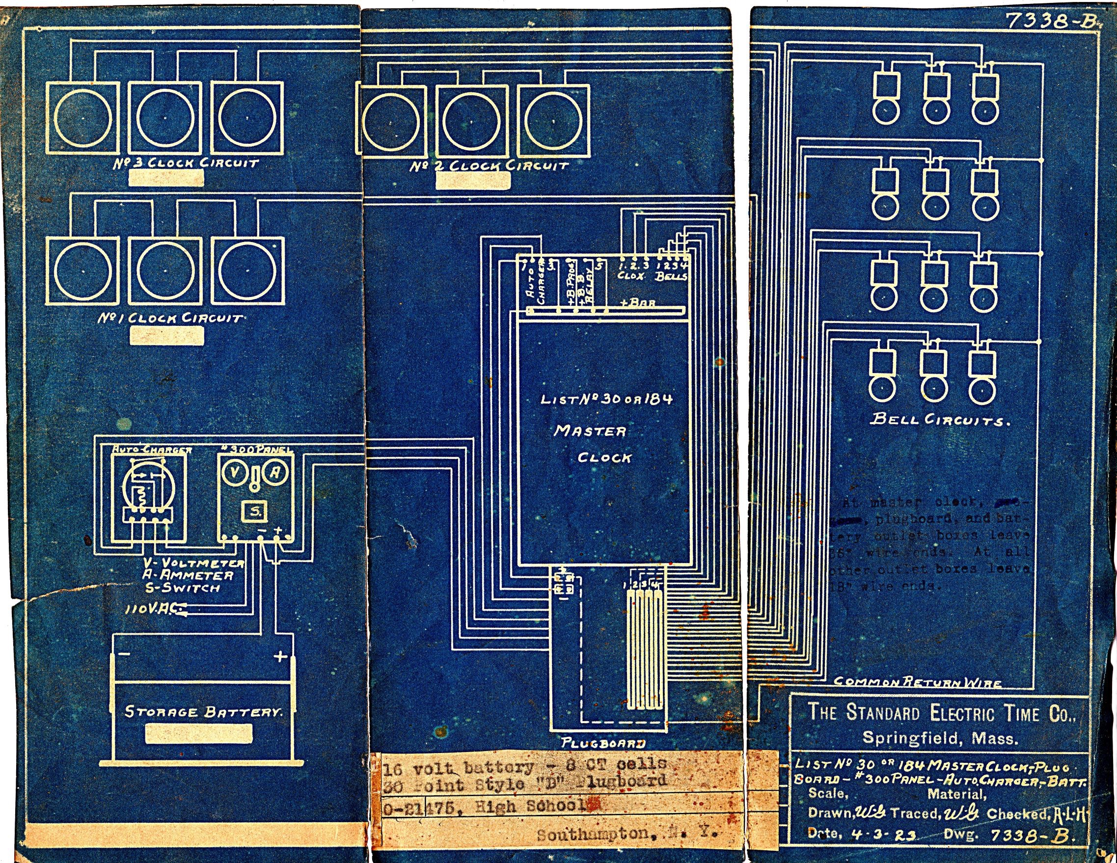
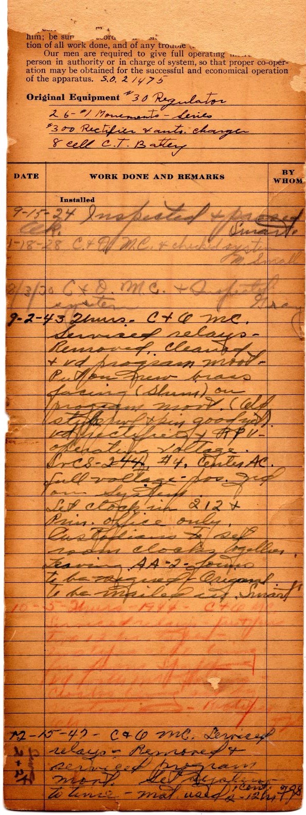
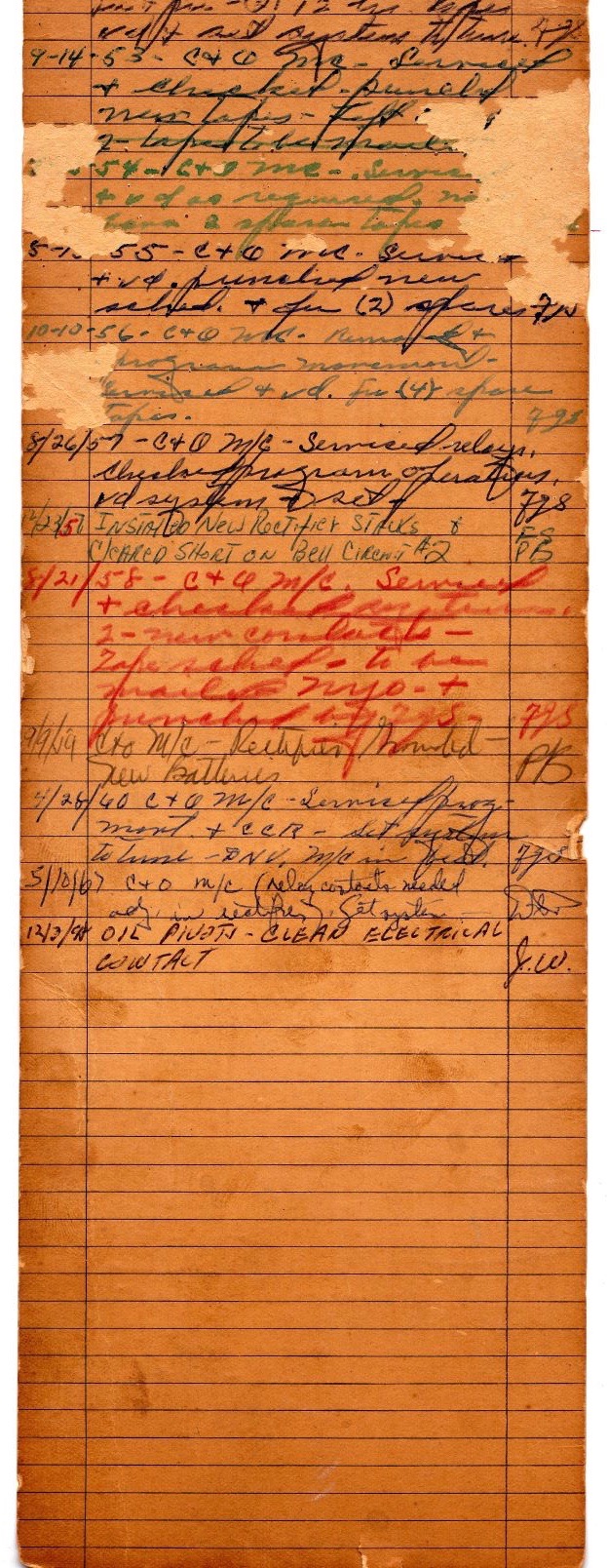
The High School�became the Southampton Town Hall in 1970 and the clock must have been removed�about that time.� This was converted at one time to a�DC transformer power and batteries were removed from system. (The transformer is located in bottom of case).
Also shown are�service�notes from 1924 and 1967.
.jpg)
This is one of four different battery powered electric clocks in our collection.� We recently repaired�a Bangor Electric that is running successfully on battery power.� It has a remarkable movement design.��The Spinney family�of Port Jefferson Village donated�250 clocks to the Historical Society that are separately housed in a three room one story building on the property�of the John T. Mather (shipbuilder) home circa 1840-1860.� There are also various outbuildings consisting of a sail loft, country store, barbershop, carriage shed etc�.��The Spinney Clock Guild (30+ members) was established around 2002 and provides for the repair and maintenance of the clock collection along with providing instruction classes on clock operations and repair.
I help in writing a monthly�article for the Historical Society Newsletter�usually covering�a select clock of the Spinney collection.
Note that Port Jefferson Village was major shipbuilding port in the 1800s and also know for its Automobile Hill Climb that started in 1909.�
Jim Boyd
Spinney Clock�Guild
Port Jefferson, NY
~ ~ ~ ~ ~ ~ ~ ~ ~ ~ ~ ~
Jeffrey R. Wood, creator of the Standard Electric Time Co. (SETCO) pages of clockhistory.com, passed away in August of 2018. I will maintain the SETCO web pages in honor of Jeff, but will not be making any additions or changes, or answering any questions. It is hard to express how much I miss Jeff, his friendship, and his wonderful contributions to Standard Electric and Westclox research.
Bill Stoddard